
CAMERA
CAd Modelling of Built Environments from Range Analysis
|
LRM
in CAMERA project |
CAMERA Homepage |
|
|
CAMERACAd Modelling of Built Environments from Range Analysis |
The European Research Network CAMERA aims at the automatic acquisition of architectural CAD models of already build environments using various techniques and approaches including range sensors, computer vision, projective geometry, photogrammetry and CAD modelling.
|
1- Range data acquisition
- Characterisation - Evaluation / Comparison |
2- Multisensory integration
- 3DLS + Video |
|
3- 3D reconstruction
- Increase the 3D reliability with data fusion |
4- Perception planning and execution |
Within the project CAMERA, IST/ISR leads the task aiming at the performance
comparison of the various 3D Laser Scanner (3DLS) available in the consortium.
A selection criteria was established for performance comparison. This
criteria includes the accuracy, the repeatability, the data quality of the laser
range measurement and the associated scanning device, denoted Pan and Tilt
Scanning Device (PTSD).
We propose an evaluation procedure to assess the reliability of the laser range
acquisition systems. First, we introduce the parameters most commonly used to
characterise the scanning devices. Then, we describe the technical
specifications of commercially available scanners and propose a 3DLS
evaluation criteria for CAMERA applications, based on a figure of merit.
Finally, we describe an evaluation process, to enable the project partners to
compare the performance of scanner sensors on CAMERA application and to share
this information. The figure of merit, as a function of the performance
evaluation, integrates 3DLS geometrical aspects (defined by equations) and
statistical ones (evaluated by experiments).
The LRF laser range measurement error and the PTSD angular
unreliability define an imprecision volume
(Figure1)
. This volume is simplified as a parallelepiped rectangle,
(Figure2)
, in which the maximum positioning error is defined as the farther point from
the parallelepiped's center. A radial 'rdl' and a tangential 'tgl'
metric components state this maximum positioning error.
A laser range measurement aims to determine the position of a point, but it is
operated on a surface resulting from the projection of the laser beam
(footprint). The maximum positioning error resulting from the footprint shape
is stated as a function of the laser beam footprint and the laser beam incident
angle to the surface containing the point to localize
(Figure 3)
. During a measurement (in a LRF integration time) the laser beam is moving,
consequently the distance shown in
Figure 3
increases. The SMAW (Single
Measurement Area Width) states this increase as a function of the distance, the
integration time and the PTSD scan speed. The footprint shape error 'fp' is
then state as a function of the distance shown in
Figure 3
and the SMAW.
The figure of merit Q, is stated at the norm of the vector
resulting from the 3 error distances, 'rdl', 'tgl' and 'fp'.
|
|
|
The radial, tangential and footprint shape induced error have been estimated for IST/ISR 3DLS (for more details, contact us ). The maximum positioning error, Q, IST/ISR 3DLS could report for a measurement, considering a large variety of target's reflectivity (from very dark one to very reflective ones), with a LRF integration time set to 10 ms and for incident angle less than 45 degrees is represented as a function of the distance and the PTSD scan speed in Figure 4 . We may conclude that for scan speed lower than 30 degrees/s the maximum positioning error the 3DLS could report is about 10 cm.
3D Laser Range Scanners are not prefect sensors, being submited to several
geometric and statistics measurement error sources, as we studied in our first
activity in CAMERA project.
3D range data segmentation and modelization are not perfect processes, and
besides of that that they are affected by the unreliability of the acquired 3D
range data.
Data fusion could compensate some errors. 3DLS range and video data fusion, in
a Projective Geometry context, is a good procedure to compare what is acquired
and modelized by a 3DLS sensor with what is observed in a video camera plane.
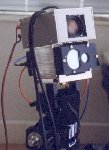
As we have a fixed position between the 3DLS and the video camera (they are
both superposed on a PTSD),
setup
, we will be using calibrated procedures. Therefore the projective relation
between a point in the 3DLS base and the video
camera one is known. The camera model used is from
Heikkilä & Silvén
, we take into account 4 parameters for camera lens distortion (2 degrees for
radial distortion and 2 for tangential one). The 8 intrinsic parameters are
polynomialy approximated as a function of focus and zoom step position. The
extrinsic calibration is done using 3D features from 3DLS range image analyse
and corresponding 2D features from video image analyse.
If a significative difference of space feature localization and / or
orientation is detected, decisions could be taken to improve the final 3D model
of an area, namely operate a new laser scan focused in the ambiguous area, give
some constraints to the 3D modelization process, or directly use some
projective geometry rules to correct the position and / or orientation of the
3DLS modelized features. This motivation is detailed in
Figure 5.
|
3DLS: LRF [ Riegl , LD-90 3100HA-GF] + + PTSD [ Directed Perception , PTU 46-17.5] +
+ Video camera:
Sony EVI-371-DG
|
|
LRM : Land Mobile Robotics Laboratory: CAMERA staff: G. Noé and M.I. Ribeiro
VisLab : Vision Laboratory: CAMERA staff: J.A. Santos Victor
ISR web site: "http://www.isr.ist.utl.pt/"
|
|
|
|
|
|
|
|---|---|---|---|---|---|
| ©1999 LRM, Maria Isabel Ribeiro , Guillaume Noé | 28-July-1999 | ||||